Friday 29 January 2016

Quantifying cooling

A few months ago +Neil Darlow mentioned that he had replaced his Mendel90 fan with a quiet version and it seemed to give better cooling results. This made me curious because quieter fans of the same dimensions generally spin slower and produce less airflow. So I purchased one to compare but then realised I had no better way of judging its efficacy than holding my finger in the air stream to feel the breeze. With these two fans it was too close to call.

After a bit of Googling I found that an easy way to measure localised airflow is with a hot wire anemometer. These heat a wire by passing a current through it and then measure how much the airflow cools it. The current and voltage can be used to determine both the resistance and the power dissipation using Ohm's law. The resistance can then be used to determine the temperature knowing the thermal coefficient of the metal that the wire is made from. The extra heat loss due to the airflow is proportional to the square root of the flow rate.

A popular circuit configuration is a constant temperature anemometer as described here, but note the op-amp inputs are labelled incorrectly. An op-amp is used to adjust the voltage across a Wheatstone bridge to keep it in balance. The bridge consists of three fixed resistors and the hot wire, so when it is balanced the wire has a known fixed resistance determined by the other three. Because the power is controlled to keep the resistance constant it follows that the temperature of the wire is constant. The voltage on the bridge can then be used as a measure of the heat carried away by the airflow.

Tungsten is commonly used for the hot wire, presumably because it has a reasonably high resistivity, temperature coefficient and resists oxidisation. I hatched a plan to use a small light bulb with the glass removed, mount it on the bed of a printer and move it around under the fan duct to plot a map of the airflow.


This is a small 12V 0.8W bulb. Its cold resistance is about 15Ω but more than ten times that when hot. This is why bulbs take a massive surge current for a few milliseconds when they are switched on.

I was wondering about how I was going to calibrate the airflow reading but then realised that the flow rate is not actually what I am interested in. It is the cooling effect the airflow has, which is what I am directly measuring. The result is simply the extra power needed to maintain a target temperature and is a measure how fast the bulb filament is being cooled. So rather than an anemometer I decided to call it a coolometer. Unfortunately Futurama used that name first. Rather than displaying megafonzies mine displays milliwatts!

This is the circuit that I came up with: -


R1, VR1 and the bulb filament connected across J3 form the bridge that is maintained in balance by U1, Q1 and Q2. The CA3140 is a fairly old op-amp that I have had lying around for more than 25 years but it does still seem to be available. It was notable at the time for the fact its inputs are happy at or slightly below the negative rail, so it doesn't need a negative supply, unlike a lot of early op-amps like the 741. It also has a very high input impedance but that is no benefit here. Its output can't go higher than 3V when driven from a 5V supply and although it can source 10mA it can only sink 1mA.

Q1 is a PNP emitter follower that amplifies the current that can be sunk and also acts to shift the output voltage range 0.7V higher. R3 and R2 further shift the voltage so the output swing can turn Q2 fully on or off. The side effect is they reduce the loop voltage gain but Q2's voltage gain will more than make up for that. It further boosts the current to drive the low resistance bulb and allows the bridge voltage to swing over the full supply range. If I was designing using modern components I would use one of the true rail to rail op-amps from Maxim and save a transistor.

VR2 is an offset null adjustment. I didn't think one would be needed at first because a small input offset isn't going to affect the output much in this circuit. However I soon realised that there are two stable states, one where the bridge is in balance and the other where the voltage supply to the bridge is zero. To force the circuit into the non-zero state I had to ensure there was a small but finite negative input offset.

I was a bit worried that adding more voltage gain after the op-amp might cause it to oscillate like my ULDO regulator did. However it appears to be stable with just the op-amp's internal frequency compensation. That must be because the transistors have a much higher frequency response than the op-amp, so don't add much extra phase shift within its bandwidth.

To measure the results, display them and send them to a serial port I used a MicroView. This is a tiny module combining an OLED display and an Arduino. I got four of these from the Kickstarter campaign. They are relatively expensive for what they are but I got four for the price of two because Sparkfun sent the first ones out without a bootstrap and had to replace them all. Since I have an ISP programmer it was trivial to install bootstraps into the first two.


The MicroView measures the voltage on the bridge and also the voltage across the bulb. With those measurements and knowing the value of R1 it can calculate the resistance and power dissipation of the bulb. Given the thermal coefficient of tungsten and cold resistance of the bulb it can estimate its temperature.

I didn't use the USB serial converter that goes under the MicroView because I wanted a micro USB socket rather than a full sized plug and I also wanted a lower profile, so I used one of these instead.

I removed the right angle connector and fitted pin strips down the two sides. They appear as J1 and J2 in the schematic. I also removed the 3.3/5V jumper and replaced it with a wire link to lower the profile.

Because I wanted to test the circuit on a breadboard and then move it to perfboard I decided to try out fritzing. I was impressed by its ease of use. One bugbear of mine with traditional ECAD is the separation of the schematic and layout into different programs. You have to export your schematic as a netlist and import it into the layout program. Then there are horrible things like back annotation and cross probing. I have long argued it should be a single model with two views that are kept in sync. Having written a UML CASE tool myself, which has 15 different tabbed views of the same database that are always in sync I know this isn't too difficult to do.

Fritzing has breadboard, schematic and PCB views that are all synchronised. You can add, remove and connect components in any view and it will be reflected in the others. One thing I found quirky was that nets seem to preserve the order of connection, so you have to route the PCB or breadboard in the same order as the schematic. You can get around this by making tracks double back over themselves but in my mind a net should represent connectivity without an order of connection.

You can find the fritzing project here: fritzing.org/projects/coolometer

Here is my perfboard layout: -


You can see the offset null pot was a late addition connected with flying leads on the back. I left the un-routed rats nest to represent those.

I am not a fan of the radial components being shown on their sides. It makes some sense for simple breadboard projects but I would prefer a strict plan view.

The breadboard view can show a traditional breadboard or  stripboard. The perfboard view is just a variation of the stripboard pattern, it simply replaces the strips with pads. The problem is that with perfboard you also need to put wire tracks on the back of the board as well as jumpers on the top. There is no way to represent that in fritzing 0.9.2, so I had to print it out and hand mark the underside tracks with a pen to actually be able to build it.

There are quite a lot of part libraries about that contain parts aimed at hobbyists like the MicroView. As they are contributed by different people / companies there are inconsistencies in the sizes and style of schematic symbols. For example the pots should be the same size as the other resistors and being trimmers should have a flat slider instead of an arrow. The arrow should meet the zigzag, not go through it, that would be a two terminal variable resistor. This appears to be a cross between the two. As fritzing appears to be aimed at education I think it is important for the symbols to be correct.

I do like the old school resistor symbols but they were replaced with boring boxes by standards organisations in the nineties if I remember correctly.

I failed to find a part for the CA3140, so I used a random op-amp that had a sensible looking symbol. Unfortunately the offset null pins of an OP27 didn't match the footprint of a CA3140, hence why it appears to be connected to an NC pin on the schematic. I tried to modify it to match my part but failed. Part creation is external to fritzing.

I also made a PCB layout just to try it out, I have no intention of making a PCB as this is a one off for an experiment. Auto route works but is ugly, as always, so I hand routed it as I always do.


A view with the pictorial version of the components would be nice. Note that the footprint of the pots is different to breadboard view. It actually matches the pots I used though.

Again it is very easy to use for simple designs like this. I think it is limited to two layers and I don't think it can do thermal vias. It can do copper fills. I will probably stick with KiCad for more complex designs.

Here is the built up perfboard version. Note that this picture was taken before I added the offset null pot.


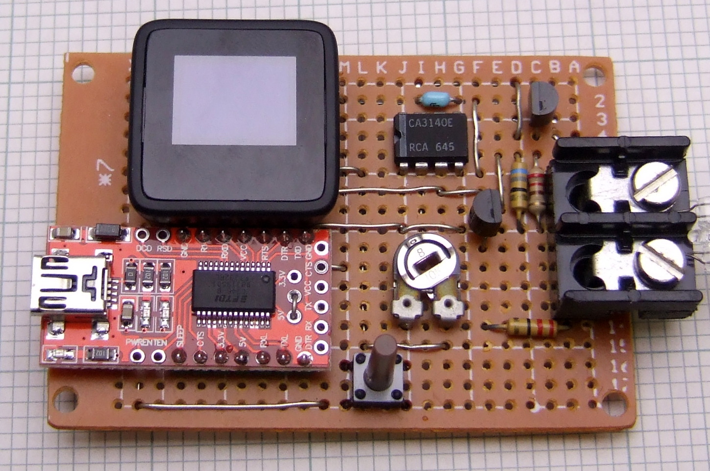
Here is the underside :-


I made a 3D printed case of course, using OpenSCAD. It was a great help that there was a 3D model of the MicroView case parts available in STL format. I was able to assemble them to make an accurate 3D representation of it and also use it to cut the hole in the case lid. Once I had measured up the perfboard I was able to locate all the components that needed holes in the case by using their grid coordinates. Amazingly this was right the first time I printed it.


I used HEATFIT brass threaded inserts which I pushed in using a soldering iron with a conical bit.


Here it is assembled and running. Unfortunately the camera shutter missed the most important bits of the text, the temperature and power.


The cheap perfboard I used was a bit warped so the board is sandwiched between the top and the base, supported all around its edges top and bottom, and clamped with four screws. The screw heads are recessed into the base so that it sits flat.

When I was following instructions to install the MicroView bootstrap I discovered CodeBender. This allows you to store an Arduino project in the cloud, edit it in a web page, compile it in the cloud and download into an Arduino using a web browser plug in. It's much more convenient than installing hundreds of megabytes of Arduino IDE and the editor is much nicer. Here is the actual code: Click on the title to see a non-embedded version in its own webpage.

The MicroView doesn't have any separation between the analogue and digital power rails so I guessed the ADC readings would be quite noisy. I knew that the AVR can be made to sleep while the ADC is sampling to reduce the amount of digital noise. I scraped some code from the Arduino forum to do that. Ten bits is not a lot of resolution so I do 16 reads in quick succession and add them together to get a 16 bit result. In the presence of random noise oversampling can increase the resolution at the expense of the sample rate. Marlin firmware uses this technique for reading temperatures.

The ADC uses the 5V rail for its reference but the actual voltage at the end of a USB cable is somewhat unknown, so I measure the internal bandgap reference to calibrate the other two voltage readings.

Once the glass is removed from the bulb the voltage becomes quite unstable. I think this is because of chaotic air turbulence. I first noticed this effect when using a thermocouple to measure the temperature at the surface of a heated bed. The control loop might be somewhat unstable due to it having a high gain and bandwidth controlling a laggy heater. It may tend to over correct and overshoot. Despite this I found that averaging over 100 samples gave a stable reading.

The firmware displays the three voltages it measures (VCC, the bridge voltage and the bulb voltage) averaged over the last 100 samples. It also displays the calculated power and temperature of the bulb.

I adjust VR1 to set the temperature to 185°C to emulate freshly extruded filament. I don't think the exact temperature matters much. Making it higher increases the sensitivity but there may not be enough voltage to maintain it in a strong airflow. Also you probably don't want it glowing as it might oxidise. It takes a lot more power to reach a given temperature once the glass is removed, obviously, as you have convection cooling even in still air rather than just radiation.

Pressing the button causes it to subtract the current power level from subsequent readings. That is done in still air so that the power reading is then just the extra heat carried away by a moving airflow.

The serial protocol is minimal. If it receives z it zeros the power and replies ok. If it receives s it clears the sample buffer and replies ok. After it gets 100 samples it sends VCC, the bulb power and the bulb temperature.

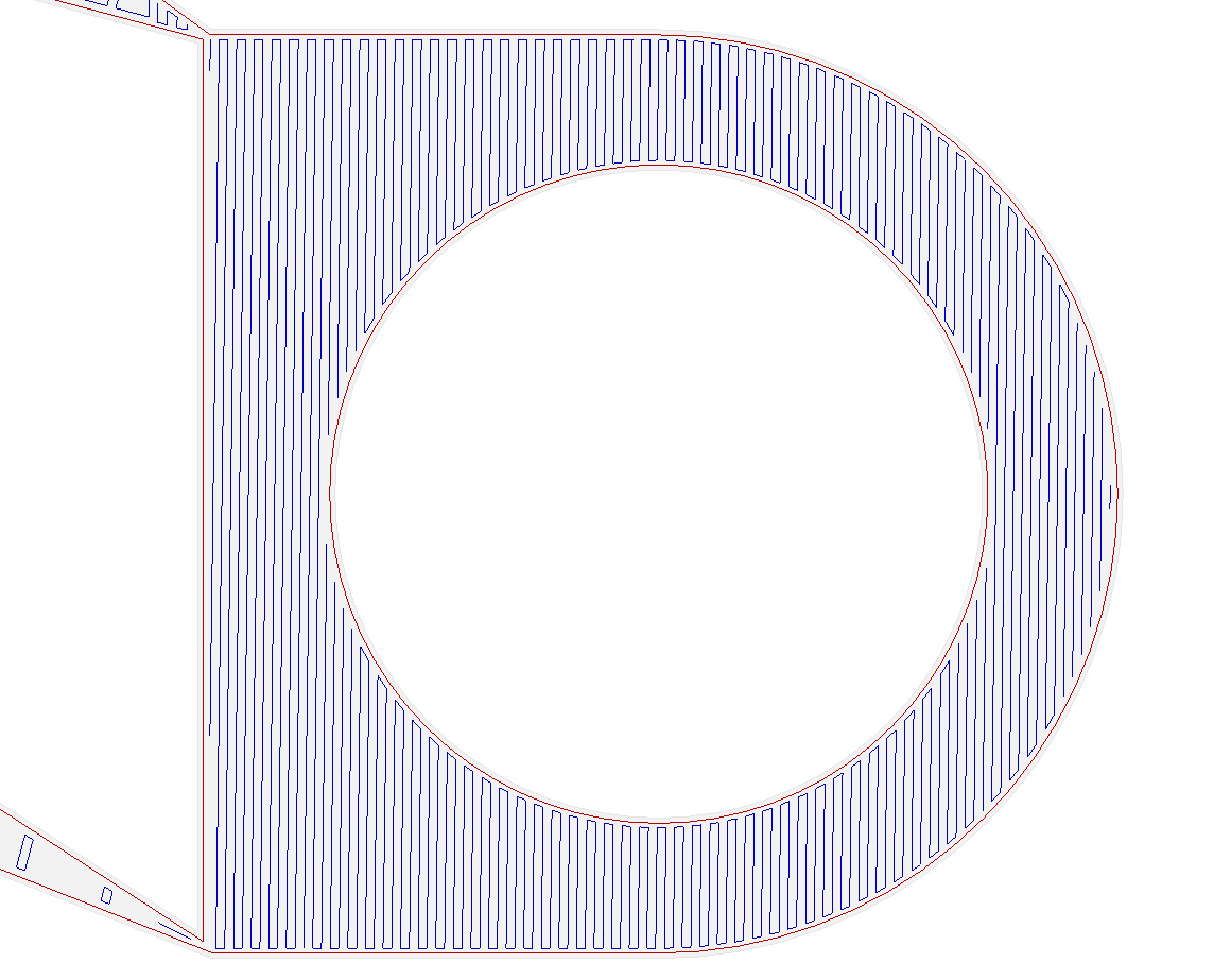
As this article is long already I will show the results in another post. In the meantime here is a scan of the standard Mendel90 fan duct's cooling effect at 2mm resolution.


Thursday 28 January 2016

A bridge too far

This version of the Mendel90 fan duct that accommodates the E3D V6 hot end happens to be a shape that is surprisingly difficult for slicers. It is because of the shallow sloping slanted bridge.


Skeinforge

I slice everything I print with Skeinforge, so the normal Mendel90 parts are designed around its limitations. It normally does a good job of detecting bridges and aligning the infill to span the gap. Its big limitation is that it does the infill for an entire layer in one direction, whereas it should at least be per island. However, even with the original flat fan duct it doesn't see the first layer of the roof as a bridge.


Left to its own devices it does this for the bridging layer.

Layer before roof: -


First bridging layer: -


Clearly this doesn't print well because the ends of the infill don't land on anything. The orange section of infill has nothing under the yellow internal edge, so the loops just fall down.

Filament runs can't start, end or change direction when there is nothing under them, whether it be infill or outline. I don't know what algorithms slicers use but if I was writing one I would generate the infill for an island at the default angle and then check that all the end points land on something below. If not then I would try aligning it with each of the straight sides of the outline, starting with the longest first, noting how many endpoints miss. In most cases that would yield a direction with no misses. In the unlikely event it didn't then I would go for the direction with least misses and try reducing them by tweaking the angle. If there is no solution then I would issue a warning and miss out the lines that can't be printed.

To get around Skeinforge not spotting the bridge I set the infill starting angle to 90° so that the first bridge layer happens to be in the right direction anyway.


This workaround is OK when you have just one layer that bridges. With multiple layers you might need to slice with different angles and then splice the gcode together, but that is getting very inconvenient.

I normally print Mendel90 parts with 0.4mm layers, but I print the duct with 0.35mm layers in order to stretch the filament tighter, so that it bridges the large gap with less droop. The fact that it isn't detected as a bridge means that special bridging settings can't be applied.

When it comes to the new duct this strategy doesn't work because every layer of the sloping bridge advances left with nothing underneath. So consecutive layers are all bridges at the left edge. With normal 90° infill rotation every second layer has its infill changing direction in mid air. It is supported a little way back, so only small loops hang down, but that makes the inside of the duct very ugly and can't be good for airflow. Also if I print it with 0.35mm layers then the extra tension makes it tend to curl upwards and brush the nozzle, leaving brown marks on the top surface.

I could set the infill rotation to zero so that every layer is the right direction for the bridge but that would lead to a weak object, especially where the infill is sparse, so I haven't tried it. What is needed is a slicer that can split the sloping roof layers into a left unsupported edge that is printed as a bridge and the rest that is printed with normal diagonal infill. I know that other slicers can have different infill patterns within one island, so I decided to try them out with this object.

Cura 15.04.3

Cura seems to display infill as solid yellow in its layers view, so I used gcode.ws to display the gcode.

Cura doesn't detect a bridge and just uses diagonal infill all the way. Interestingly it doesn't connect the ends of the infill, it does a short move at high speed with no retraction. Also it doesn't seem to have any retraction when it moves significant distances across the infill. This is one of the reasons I don't use Cura. I need retractions before all moves longer than say 1mm otherwise it leaves a trail behind and the next line doesn't start properly as there is missing plastic.

KISSlicer 1.1.0.14

KISSlicer shows some errors in the STL but the colour it uses to highlight them isn't in the key, so I don't know what it thinks is wrong. There are no errors in Netfabb Basic so I am pretty sure the file is OK.


It too doesn't recognise the bridge and just does normal diagonal infill over it, using a colour scheme that is very difficult to see!


One odd thing is seems to do is inset the internal walls a little further on the last layer below this one, perhaps to give the infill more area to land on.

Slic3r 1.2.9

Slic3r actually detects it as a bridge but gets the angle slightly wrong.

Two infill lines start or end in mid air. I discovered though that if I rotate it 90° the infill comes out correct.

This is a shame because I orientate it length ways for printing. That is because on a moving bed Y axis you want to minimise the Y movement to keep the object in warm air.

The next layer does exactly what I want. I.e. it does horizontal infill where there is nothing underneath but reverts to normal diagonal infill where there is something below.

So far so good but after a few more similar layers it starts to go a bit wrong.

It gets the boundaries of the bridge region wrong. It has a few lines of infill turning in mid air at the right hand side. Further up the slope it gets the left hand side wrong as well. I suspect it is because the slope slants left to right.

Further up it gets a bit more strange.

I haven't tried printing it but I suspect it would come out not too badly, with just a few small loops hanging down. At least it does logically the right thing, shame about the bugs in getting the bridge angle and region accurate.

CraftWare 1.13 beta

This is a late addition suggested in the comments. Perhaps the nicest user interface of all but it doesn't detect bridges at all in this object.


Simplify3D 3.0.2

Since none of the free slicers I know of got this right I decided to try a paid for one. With a single outline it fails to detect the first bridge and just does diagonal infill in mid air.


On subsequent layers it does seem to divide the layer correctly into a bridge region and a normal region but gets the infill direction in the bridge area completely wrong.


With two outlines it gets the main bridge correct but the slope now doesn't have a separate bridge region, just diagonal infill. That is except for just one layer and that also has the direction wrong.


 The odd layer corresponds with the solid support diaphragms over the screw holes.


This does print slightly better than the Skeinforge one but only because the extra outline means the infill lines don't need to overhang quite as far.

Conclusion

So in summary I can't find a slicer that gets this correct but Slic3r is the closest. Of course they all offer support material but that would be difficult to remove inside the duct and there in lies another raft of bugs, if you pardon the pun. See below: -


Wednesday 27 January 2016

Telequipment D32 trace rotation fix

Another ancient piece of equipment I have is this Telequipment D32 mains / battery operated portable oscilloscope.


Telequipment is an old brand name used by Tektronix in Europe. I think it was made in about 1972 for servicing TVs. I bought it in a broken state from a friend of a friend in the mid 1980s. The six NiCad D cells had gone short circuit and the mains transformer was burnt out. I replaced both of those and as far as I can remember that was all I had to do to get it working.

I did get a lot of use from it as for many years it was the only working scope I had. I haven't used it much in recent years though because I now have several much better scopes. It is the only battery powered one I have, although I do have two USB digital scopes which are battery powered if I run them from a laptop.

I powered it up fully expecting the NiCads to have died again, but amazingly they still work to some extent. The only thing wrong with it was the trace was slanted and the trace rotation control didn't have enough range to correct it fully. It seemed to max out in one direction and then have a large dead band.

I did a bit of research and managed to find the schematic. I must admit that somehow the fact that a beam rotation circuit is needed because of the earth's magnetic field had completely passed me by, or else I once knew and have since forgotten. This is despite building my own scope with valves (vacuum tubes) when I was 13 and using CRT scopes for many years after.

The rotation circuit is below. After looking at it and making some measurements I was surprised to find it to be a design fault rather than a faulty component.


The base of TR301 can be varied between ±7.5V with R303, so one would expect the emitter follower to drive the coil over that range with a VBE offset. The problem is the coil has a resistance of about 1kΩ, so the pull down resistor R314 can't drag it below -3.5V. This means the control has no effect for a significant part of its travel and the range of the correction is asymmetrical.

To fix the problem I removed R314 and replaced it with a PNP emitter follower. That gives push-pull symmetrical drive between about -6.8V and 6.8V. The only dead band is a small one around 0 due to the VBE drops (classic crossover distortion). It also has the advantage of not wasting the current through R314, all the current now flows through the coil.

This is a view of the board before the mod. It is ancient technology, all discrete transistors and hand routed PCBs, including vias made with what looks like soldered in brass rivets.


I don't know why all the transistors are socketed. The only other time I have seen that was in a Russian transistor radio, but they were germanium PNP transistors, so may have been unreliable. These are silicon planar epitaxial so should be reliable and never need replacing. Perhaps they did it because they thought soldering would damage them. Or perhaps they were just old school designers used to valves.

Anyway the scope is a joy to work on because all the PCBs hinge out to allow access to both sides with the scope still operational. See www.youtube.com/watch?v=BOeEbyIllcM for a look inside a D32.

Here is a view of my modification: -

I replaced R314 with a 2N4403 (any PNP transistor should work) and linked the base to a handy via. Don't worry about the proximity to the ceramic capacitor's lead, it is the same net.

So a simple mod but I don't understand why I need it now. Perhaps the earth's magnetic field has changed since I last used it. It was about a decade ago!

Update

The scope has always had a delay between switching on and starting up. The power LED comes on about a second after it is switched on.  This got longer and longer and then it stopped starting reliably at all. I had always assumed the delay was caused by a capacitor charging in a bias circuit for the inverter but on examination of the schematic I fount that wasn't possible because all the capacitors have a low impedance supply.

It turned out the be the on off switch. I measured about 3V across it in the on state. The contact resistance measured 0.3Ω but that should only drop 0.3V at 1A, so it seems to be a strange non-linear resistance and it must get lower over time as it heats up.

The switch is part of the brightness potentiometer and it is operated by pulling the knob out and pushing it in. Normally potentiometers with switches operate it at the start of the rotation but this allows the brightness setting to be retained. It is also a small form factor so I didn't think I would be able to find a replacement. As it is riveted together I didn't think I would be able to repair it or even get any switch cleaner into it.

It is actually a two pole switch, the second pole is used to change the charge current of the battery to include the scope current when on. I figured 0.3Ω would not affect that circuit as it has 150Ω in series, so I swapped the connections over. It now starts instantly although it does take time for the tube to warm up of course.

Tuesday 26 January 2016

Tektronix 8560 still going strong

And now for something completely different...

I have been tidying my lab post kit production to make room for future experiments. In the process I have been skipping loads of junk. I do have trouble throwing things away that work just as well as when they were new and expensive but are now utterly out of date and superseded by much smaller,  better and cheaper things. I power them up periodically to test them and hope they might fail and give me an excuse to chuck them.

I powered up an old PC and six electrolytic caps exploded in quick succession, sounding like a distant firework display! Presumably a victim of the great capacitor plaque in the early 2000s. Remarkably it still managed to boot into XP but it had signed its own death warrant and went straight to the skip.

Several more PCs with only 256MB of RAM went when I found they wouldn't even load a supported version of Linux. Only a Shuttle with 1GB of RAM that successfully runs LXLE survived the cull.

I also have a Tektronix 8560 multi-user software development unit that is actually a DEC PDP11-73 mini-computer in a 19" rack with a Kennedy Model 9000 open reel tape drive and a Dylon Model 1015B Magnetic Tape Controller.


It was purchased by the company I worked at for £48,000 in 1984 and supported 8 software developers on dumb terminals connected via RS232. They gave it away for nothing in the early 90s.   To put that in perspective £48,000 would buy a decent house in 1984 that would have been worth a lot more in the nineties. Computers must be the worst investment ever! The rack is probably the only bit that retains any value.

It has 1MB of memory on two large cards and the processor is only about as powerful as an Intel 286, but with a much nicer instruction set. We had to write PDP11 assembler in some university workshops and it is the nicest instruction set I have come across.

It was replaced by two MicroVaxes and later PCs of course. The ironic thing is it replaced Motorola  EXORcisers, which were single user desktop computers, so things sort of went in circles.

When the machine was delivered it had a PDP11-23 but the embarrassing thing was it didn't perform as well as the 8 bit EXORcisers because, although it was a 16 bit processor with 1MB of memory, each process had to fit both the instructions and data into a 64K segment, just the same as the 8 bit machine. The 8 bit linker program was smaller so there was more room for the target program. We had to immediately upgrade to the PDP11-73 CPU that has separate instruction and data segments allowing the full 64K to be used by a process for its data. I still have the original processor: -


It runs Unix version 7 re-branded TNIX. It is built like a tank, so of course it still powers up fine, asks if the time and date is still 2006 (the last time I powered it up) and if not suggests I enter a time and date with 1982 as an example. No Y2K bugs here!

It is nearly as loud as a vacuum cleaner and smells of burning for the first few minutes. I think there must be a thermistor or a dropper resistor in the PSU that quickly gets very hot and burns off the dust.

Even the tape drive still works once I had remembered how to set it up, but it only holds about 20MB and would take something like an hour to write that much. The only thing that failed is the foam block that holds the end of the tape in place in the spool. It has started to disintegrate as foam seems to do eventually.

It is in need of a good home but I think it is too modern and not rare enough for a Museum. One day I might skip the insides and use the case to house a big 3D printer or lots of little ones.

Monday 25 January 2016

Ultra Low Dropout Regulator for flicker free LEDs

Cheap 12V LED lighting strips are very sensitive to small voltage changes. This is because they just have multiples of three white LEDs in series plus a small resistor to set the current. The voltage across the LEDs is more or less constant at 3 × 3.2V, so the resistor sees the difference between that and the supply voltage, around 2.4V. This means that a 10% change in supply voltage produces around 40% change in current and hence brightness.

ATX PSUs have poor regulation on the 12V rail but this doesn't affect the rest of a 3D printer because everything is regulated downstream. The stepper drivers are constant current and the heaters are temperature controlled.

Here is a dip in the 12V rail caused by the 10A bed switching on. As you can see the swing is 12.2 to 11.6V, around 5%. This results in about a 20% reduction in light which is very noticeable.


One way to fix the problem would be to make an accurate 12V from the unused 5V rail using a small boost converter. I didn't want to cause any EMC issues, so I decided to use a low drop out (LDO) regulator to regulate to just below 11.6V. I thought it would just be a single chip solution, but after a lot of searching, the lowest drop LDOs I could find were 0.5V and I didn't want to waste that much.

I decide to roll my own using a low RDSon MOSFET as the series element. The LEDs only take about 0.5A, so the drop out voltage with a MOSFET with an RDSon of a few milliohms can potentially be a few millivolts, hundreds of times better than any LDO chip I could find.

In practice I used a BTS134 MOSFET I had lying around with an RDSon of 60mΩ. To put that in perspective that is less than the voltage drop in the wires I used.

This is the circuit I came up with: -
I regulate the negative side of the LEDs so that I can use an N channel MOSFET. Virtually any logic drive MOSFET should work. I wired this after my RPi switching circuit described here: hydraraptor.blogspot.co.uk/2014/06/lights-camera-action.

I use a TL431 adjustable precision reference as the control element. These are great little chips that can do anything from replace a zener diode to being an audio amplifier. The green LED acts as a level shifter to ensure the cathode voltage of D1 is higher than the reference voltage, a requirement of the chip. A white LED would give more margin.

VR1 should be initially set for the maximum output voltage and then gradually reduced until the flickering stops when the bed is switching. Handily the green LED flickers when the LEDs are flickering aiding adjustment without being blinded by the light.

C1 prevents the circuit oscillating at about 50kHz by providing negative feed back. I found its value by trial and error as there wasn't any phase shift versus frequency data in the data sheet. Basically R3 and R4 form an RC network with the gate capacitance of the MOSFET. This will produce a 90°phase lag at high frequencies. The TL431 must also create a 90°phase lag around 50kHz. To prevent oscillation C1 has to reduce the loop gain to less than one when the total phase shift is 180°. The circuit was stable with 1nF but had a bit of ringing. With 10nF it was a bit slow to respond.

The scope view below shows the performance of the regulator. The yellow trace is the 12V supply to the LEDs. The cyan trace is the negative supply to the LEDs (shown at a bigger scale). The purple trace is the difference, i.e. the voltage the LEDs see. It is virtually constant and the drop across the regulator goes as low as 40mV.


The maximum voltage across the MOSFET is only about 600mV (the size of the dips in the 12V rail). That makes the dissipation about 300mW, which is easily dissipated without a heatsink. Don't set VR1 too low though as the dissipation will go up rapidly.

Here is a veroboard layout done in VeeCad: -


If there is enough interest I could make a PCB to combine this with the RPi interface and also add a 5V in connector to avoid the need for the micro USB plug.

Thursday 21 January 2016

Mendel90 GitHub catch up

I finally found time to update GitHub with some Mendel90 changes that I have had in the works for a long time. The problem with releasing them sooner was that they were all not quite finished and / or would make unintended knock on changes to the kits I was producing. In particular the changes I did to make a Huxley90 in a hurry for the TCT show and the E3D mods kindly contributed by Philippe LUC that conflicted greatly with it, so needed a lot of work to merge.

OpenScad

I also updated to the latest version of OpenScad. The upside was that hull and some of the 2D operations are much faster. I was also able to replace all the calls to minkowski with offset as I was only using it for 2D offsetting. The net result is it is now four or five times quicker to generate the preview and the STL files. The downside is that the 2D sub-system now uses fixed point coordinates but the rest of OpenScad doesn't. This makes it difficult to get 2D and 3D geometry to match up. For example, an extruded circle now has slightly different vertices to a cylinder of the same size. This created a few degenerate triangles requiring that I changed the way I constructed some objects in order to get nice clean STL files.


The solution in the case above was to make the cylinder slightly bigger than the circle used to make the pointer.

On the up side it seems OpenScad has got better at handling unioning exactly coincident faces since I first wrote Mendel90, so I could remove some of my small offset bodges to avoid z-fighting.

Another benefit is that the X end brackets now slice correctly in Slic3r, as the bug that caused internal faces to point the wrong way has now been fixed. Skeinforge doesn't care about face orientation, it just counts edges to work out what is inside and what is outside. Other slicers got confused and filled in the nut cavity.


Along the way I discovered that, although OpenScad now has trig functions that are accurate for multiples of 90 degrees, etc., it doesn't use them in rotate, or vertex creation for circles and cylinders. It converts to radians and uses the library trig functions. Degrees can never be represented accurately as radians in floating point because Pi is irrational, not to mention transcendental. To get round this I now override the built in rotate with a user space version that uses the accurate sin and cos degree functions.

module rotate(a)
{
 cx = cos(a[0]);
 cy = cos(a[1]);
 cz = cos(a[2]);
 sx = sin(a[0]);
 sy = sin(a[1]);
 sz = sin(a[2]);
 multmatrix([
  [ cy * cz, cz * sx * sy - cx * sz, cx * cz * sy + sx * sz, 0],
  [ cy * sz, cx * cz + sx * sy * sz,-cz * sx + cx * sy * sz, 0],
  [-sy,      cy * sx,                cx * cy,                0],
  [ 0,       0,                      0,                      1]
 ]) children();
} 

Not surprisingly every STL and DXF file generated is now slightly different numerically but hopefully not dimensionally. I made a stable branch to record the state before these global changes, just in case. GitHub has some excellent image and STL comparison views but unfortunately it gives up if more than a handful of files have changed and there are hundreds in the Mendel90 tree.

Wade's Block

After a few people started to report broken or cracked Wade's blocks I strengthened it a bit around the bearing block. I also made the bearing sockets a bit bigger so there is less stress created pressing them in. Kits from around March 2015 have shipped with this version.

X Carriage

When Philippe LUC created the E3D branch he fixed a few bugs. One of these was that the X carriage top was only 2mm thick, when the design intent was 3mm. This was due to the fan duct using the same variable name. Whoops! I have updated it now in the main branch. I also made the nut traps for the fan bracket screws deeper to allow for longer screws and to allow them to be withdrawn further without loosing the nuts. This makes it easier to remove and replace the duct. Simply removing the washers is an alternative.

E3D Hotend

I temporarily parked Philipp's mods in an E3D branch until I could merge them. I have now updated the master branch to support E3D V5 and V6 hot ends with this one line change to the config file. The generated files for V6 that are different from standard build are in new folders dibond_E3D and sturdy_E3D and I have deleted the temporary E3D branch.


There is no room for the right hand wing nut because it clashes with the hot end's fan. Fortunately the carriage has always had nut traps to allow the screws to be inserted from below. A plain nut above can then be used to secure the extruder.

Primarily the things that change are the Wade's block, the fan duct and the fan bracket. The Wade's block has no extension to avoid losing more Z build height than necessary and a plain screw hole on the right end instead of the hex socket.


The fan duct has to slope downwards to avoid the E3D heatsink. That creates a sloping bridge that is also skewed horizontally. I haven't found a slicer that handles this properly yet, having tried Skeinforge, Slic3r, Cura, Kisslicer and even paid for Simplify3D! I have blogged about their failings in another post here: hydraraptor.blogspot.co.uk/2016/01/a-bridge-too-far. Any other slicers I should try?


Another bug Philippe noticed is that there was almost no clearance between the fan and the belt. Fortunately the belt is twisted so it actually does clear the fan. I have added more clearance as
Philippe did. It makes the fan bracket and fan duct 2mm longer. If you print either from the new files be sure to print both or the duct will be misaligned.

I also improved the internal shape of the duct a bit. From this: -


To this: -


It probably doesn't make a lot of difference but a comparative test of various fans and ducts will be the subject of a later post.

Even with the shortened Wade's block the E3D V6 hot end is 4mm lower and the V5 is a bit longer still. If you retro fit it to an old machine you will lose 4mm Z travel. If you are building a new machine then there are alternative files which add 4mm to the height of the frame and lengthen the Z smooth rods and threaded rods on the bom. That also has a knock on effect on the shape of the spool holders and the dust filter. If you use the larger sheets be sure to get the correct size rods and use the correct spool holder parts to match the frame.

New Lighting Options

I redesigned the lighting system I described here to work with some commonly available LED light strips. These consist of an aluminium PCB strip that slides into an aluminium extrusion with plastic end caps, which I discard. Instead of printing a bar to hang the lights and camera from I now add printed end caps to the light strip and uses those to hinge it from the frame edge clips. I then hang the camera from the strip with its own hinge.


The strips come in 500mm lengths but they can be cut at discrete points between every third LED. They are described as "50CM 5050 SMD 36 LED Warm White Aluminium Rigid Strip Bar Light Lamp" and I bought them from bgood2010 on eBay.


I got some from another seller and although the eBay picture looked the same the extrusions where actually not as deep. The STL files on GitHub are for 8.6mm deep extrusions and are generated by light_strip = RIGID5050_290. Setting it to Rigid5050_290 generates the clips for 7mm deep extrusion. Other sizes can easily be accommodated as long as they are rectangular. The definitions are here.

Rather than waste the off-cut I mount it above with a second pair of end caps that clip onto the main light strip. These are set back just far enough to avoid the build volume in the unlikely event you print something tall at the back edge of the bed. This is calculated by the model with lots of trig and Pythagoras maths. Set show_rays = true to see this view showing that the camera and lights are pointing at the centre of the bed and the build volume is clear.


Another light strip that can be selected is this one: FSRP3W, discovered by Alzibiff.


Again the end caps are removed and replaced with printed ones that clip into the screw channels in the extrusion. There is no room for the plug so I just solder the wires on.


It looks neater and gives a more diffuse light but is not as bright as the double strip of 5050 LEDs and is more expensive. I bought it from www.ledlightingandlights.com.

The only problem with these light strips compared to my original Sanken ones is that they are unregulated, so they flicker when the bed switches on and off. I described how I fixed that here. I also need to update the mounting for the Raspberry Pi to accommodate the plethora of new Pis that have appeared since my original design.

Huxley90

The Huxley version is scaled down in the same way as the Sells Mendel was scaled to make the Huxley. It has a build volume of 150mm cubed and uses NEMA14 motors, 6mm smooth rods and M3 fasteners for the frame. There is a good photo of it alongside the full sized machine on Ivor O'Shea's blog post.

The NEMA14 motors have about half the torque of the NEMA17s when driven with the same current. The Y carriage and bed have about half the area hence half the mass, so that is about right. Also a NEMA14 has half the mass of a NEMA17, so the X carriage also has about half the mass.

I believe the flex in the middle of the rods is proportional to the length cubed times the weight divided by the bar radius to the power of four. The length of the X rods is almost exactly 75% of the Dibond version and the diameter is obviously 75% as well. The relative flex then boils down to 0.5 / 0.75 = 0.67. So going down to 6mm rods is justifiable as well. Everything scales very nicely physics wise.


As the design is fully parametric shrinking it should have been easy, but because vitamins don't scale perfectly lots of snags arose where things clashed. A typical example was the x_motor_bracket. The NEMA14 motors are smaller but the raised boss around the shaft is the same size. This makes the bracket a different shape and it then needs a support to print it.


Half a truncated teardrop with a crutch!

The heated bed was made with veroboard and coincidentally has the same resistance as a full sized Prusa PCB, so the machine takes the same amount of power but heats up about twice as fast. There is no room on the frame for an ATX PSU, so I used an external XBOX 200W PSU. I couldn't find a spec for the 5V standby rail but it seems to supply enough current to power a Raspberry Pi.

Direct Drive Extruder

The extruder is where the scaling fell down a bit. The original Huxley used a Bowden drive to make the carriage small. I didn't fancy that but I didn't want to have the carriage as big as a geared extruder would need, so I went for direct drive with a NEMA14 and 1.75mm filament. 


The filament needs about one third of the force to feed and a Wade's has roughly 1:3 gearing, so a direct drive NEMA17 is about equivalent. The NEMA14 has half of the torque, so it is a bit under powered. I used the smallest drive pulley I had which was a mini hyena from Laszlo Krekacs' Indigogo campaign. Unfortunately I don't think the small diameter version is available now. I could probably make one from a hobbed bolt if I needed to or hob one from scratch.

It feeds PLA fine at 200C but isn't able to pull it off a spool. I will try a spool holder with a central bearing rather than the rim bearings to see if that is low enough friction. If that doesn't work I might try a powered filament supplier like the one on the first Up printer preserved here. Or maybe even try Bowden drive.

The design is parametric so there is a NEMA17 version suitable for Mendel90. I just need to adapt it for a commonly available drive pulley. It should just be a matter of adding a description here.

It can also use the E3D hot end but that doesn't fit between the bars on a Huxley90.


So that is Github up to date and hopefully correct although I haven't tested a lot of these changes.

I noticed that Blogger is now a lot worse than it used to be. Headings and pictures are now a nightmare.