I recently bought a
500ppm LCR meter from Elektor because I didn't have anything for measuring inductors or the ESR (equivalent series resistance) of capacitors, both of which are important for modern electronics, particularly switch mode regulators that have become ubiquitous.
It is also more accurate than any of my multimeters and has wider measurement ranges. For example it can measure resistance from 0.1mΩ to 1GΩ and capacitance between 0.1pF and 0.1F. This means I can now measure parasitics like contact resistance, stray capacitance and lead inductance. The principal reasons it can do this while my multimeters can't is because it uses a four wire Kelvin connection to the device under test, and as well as measuring voltage and current, it also measures the phase between them.
It took over a month to be delivered and the case arrived two weeks later. The meter's arrival coincided with the arrival some ridiculously cheap switch mode buck and boost regulators from China. None of them worked properly (no surprise there) so it was pressed into service straight away, without its case. It worked well but when I got the case there were a few snags assembling it and then it then didn't work properly.
The case comes pre-drilled and labelled from Elektor and is about three times the price of the generic version available from RS and Farnell. I expected it to include all the fasteners for that price but it only came with the screws that hold the case together.
To mount the LCD PCB I needed four M3 x 16mm countersink screws, nuts and washers and four 7mm M3 spacers. Luckily I already had suitable screws and I used eight 6 BA x 1/8" spacers as the LCD is actually 6.4mm only thick. If I hadn't had those I would have printed some custom plastic ones.
I found the LED was too short to reach the hole for it in the front panel, so I re-soldered it as high as I could to improve its appearance. I also chamfered the back of the hole for it with a countersink to guide it in.
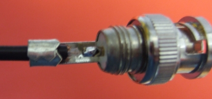
The next issue I had was the ribbon cable was way too long with nowhere to store the excess.
I shortened the cable and re-attached the IDC plug on the other side.
It is not good practice to re-use IDC connectors but I didn't have a 14 way one to hand.
The long cable did allow me to test it without the case though, which would have been more difficult with the short one.
The main PCB just slides into guides built into the case extrusion. I did have some problems with getting the LED to go into its hole so I chamfered that on the inside as well.
The body of the LED protruded a bit too far to allow the board to go all the way in so I re-melted the solder and pushed it back as far is the PCB holes allowed. That was just enough to allow a perfect fit.
The case must be earthed via a screw hole on the PCB but the the hole in the case was missing as well as the fasteners. I marked the hole position using a 3mm spot drill though the PCB and then drilled it to 3.3mm and countersunk it. This is necessary because the head comes out under the ABS end bezel. I used another M3 x 16 CS screw with a 5mm brass spacer, a shake proof washer and a nut.
When fitting the right hand end cap I noticed the USB connector shorted to the surrounding metalwork. That is not good because the USB shield is connected to digital ground but the case is analogue ground. I added some clearance by filing two sides of the hole.
After assembling the case I found it no longer worked properly in LCD mode. The open circuit trim always failed with "trim failed due to line perturbations". It still worked when used via its PC program where the LCD display is not used. So it seems the LCD PCB is too noisy to be mounted close to the analogue front end.
I concluded I needed to place a metal screen over the LCD PCB but there isn't a lot of room inside the case. My first thought was to add a sheet of single sided blank PCB material mounted on spacers with the same screws that hold the PCB. That would have involved cutting it to size, marking and drilling four holes, either manually or by setting it up on one of my routers. Being too lazy for that I decided to 3D print an insulating cover for the PCB and cover it in aluminium adhesive tape.
Here is my OpenScad design :-
And here it is covered in aluminium tape and fitted :-
I trimmed the long wires from the LCD display to reduce the clearance needed from the back of the PCB to 1.5mm. I also bent the test pins on the main board to reduce their height. I replaced the plain washers and nylocs shown earlier with shake proof washers and plain nuts. The washers dig into the aluminium to hopefully make a good connection through the oxide.
With the screen fitted the meter works again in LCD mode although the short circuit trim fails occasionally. When powered from my PC or running stand alone from a USB adaptor the readings jump around a lot. When powered from my linear bench PSU it is much more stable. This isn't surprising as PCs tend to have a lot of ground noise, particularly laptops with external power supplies. My desktop PC (3D printed case of course) is micro ATX powered from a remote 12V PSU so will have similar ground noise to a laptop.
I don't think powering such a sensitive piece of equipment from a USB switch mode PSU makes a lot of sense unless it has exceptional output filtering and a clean ground. It only takes 180mA so an old fashioned mains transformer and linear regulator could be used.
Summary
Extra Parts required
- 5 off M3 x 16mm countersink screws.
- 5 off M3 plain nuts.
- 5 off M3 shake-proof washers.
- 4 off M3 x 7mm or 6.4mm spacers.
- 1 off M3 x 5mm spacer.
- Metal screening for the LCD PCB.
Tweaks
- Drill and countersink the earth screw hole.
- Expand the hole for the USB connector to give clearance all the way round.
- Chamfer the inside of both LED holes.
- Reposition both LEDs slightly.
- Shorten the ribbon cable.
- Crop the LCD pins.
- Fit an earthed metal or foil screen over the LCD PCB.
With these tweaks the LCR meter works very well. It gives much more stable readings in stand alone mode powered from a linear PSU.
On reflection I think the design should have included a metal screening can over the analogue front end. It could then be housed in a cheap plastic case. I could have 3D printed one saving myself about £45 but it would not have looked as nice as the anodised aluminium one.